Dipl. Ing. A. Kutschelis & Sohn
Technische Lehrmittel Construktion
D- 59425 Unna
Germany
web: http://www.telc.de
mail: mail@telc.de
phone.: +49 (0) 2303 239999
facs: +49 (0) 2303 239990
| printable version | Tool dynamometer drilling BKM 2010 | |
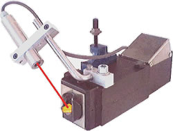
| This lightweight and practical, four component dynamometer measures the cutting forces in any drilling process. The measured values can be read on the internal display or on a large external display using auto-hold. The PC-based data acquisition is performed over the built-in USB interface with the included software for tool dynamometers. Over the same interface the device parameter setup for wear detection is executed. After the setup, the device is able to supervise a drilling process without a connected PC. With this great properties the device suits multiple educational and industrial applications. | |
Downloads: | ||
Measuring range: Axial force Ff: pressing & pulling +/- 5000 N | ||
Experiments: The cutting forces of the drilling process is measured on the workpiece which is clamped to the head of the device. Usually, this is a bar with a 40x20 mm (1.63" x 0.82") cross-section. The device itself is bolted onto the machine table. The measuring range is suitable for drilling with drills of about 15mm (0.6") diameter and feeds up to appr. 0,3mm/rev. The device is protected against liquids. The following experiments are possible:
| ||
Dimensions: Size (w x d x h): 170mm x 100mm x 100mm (6.94" x
3.94" x 3.94") | ||
Keywords: Torque meter, Cutting Dynamometer,
Tool Dynamometer, Cutting thrust meter, wear detection, break detection,
Tool monitoring, Drilling, Drill, Borehole, Power, Force, Feed, Cut, Cutting,
Burr, Temperature, Torque, Reduction of wear and tear, wear out |
||
| ©TeLC Unna 2004 | ||
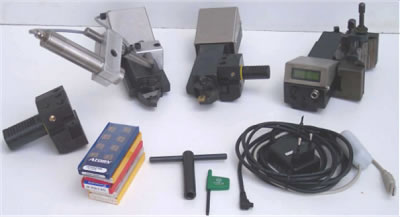
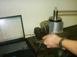
| printable version | Tool dynamometer turning DKM 2010 | ||
| |||
NEW 5- Components Dynamometer for measurement of cutting forces and tool tip temperature in turning processes | |||
DKM2010 is now a 5-Components Tool Dynamometer,
It measures
| |||
| It is as small as
the former type A, but measures forces up to 2000 N With help of the adjustable inserts holder for indexable inserts ISO type CCM..9 approach angles of 45 60 75 90° are easily adjusted. With USB interface data acquisition rate now can be adjusted up to 100 SPS . The measured values can be read on the internal display using auto-hold. The PC-based data acquisition is performed over the built-in USB interface with our included software for tool dynamometers. Over the same interface the device parameter setup for wear detection is executed. After the setup, the device is able to supervise a turning process without a connected PC. Also available is a temperature measurement of the tool tip, which is fully integrated in the device. With this great properties the device suits multiple educational and industrial applications. | |||
Downloads: | |||
Measuring systems : Strain gage sensors with very small deflection, range 2000N, resolution 1 N, data acquisition rate adjustable 5 – 100 SPS | |||
Clamping; Adjustable inserts holder : Thanks to the
bars left and right side of the body the DKM2010 can be clamped in every
turret on the lathe and be operated in longitudinal or cross feed on konventional
or CNC lathes. The bars are 12 mm high. | |||
Experiments: The following experiments are possible:
| |||
Keywords: Cutting tool dynamometer, Cutting
dynamometer, Tool dynamometer, cutting thrust meter, wear detection, break
detection, tool monitoring, Turning, Borehole, Power, Force, Feed, Cut,
Cutting, Burr, Temperature, Torque, Reduction of wear and tear, wear out |
|||
| ©TeLC Unna 2004 | |||
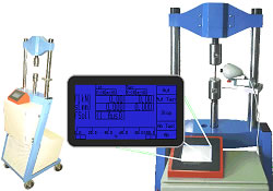
| printable version | Tool dynamometer milling FKM 2000 | |
| ||
| This six component dynamometer measures the cutting forces in any milling process. It is an improved version based on a principle existing since 1982. The measured values can be read on a large external display using auto-hold. The PC-based data acquisition is performed over the built-in USB interface with our included software for tool dynamometers. With this great properties the device suits for multiple educational and industrial applications. | ||
Downloads: | ||
Measuring range: 3-axes measurement: Fx, Fy, Fz = +/- 3000 N | ||
Experiments: The milling processes's cutting forces are measured on the workpiece. The workpiece is clamped in the dynamometer like in a vice. The device itself is bolted onto the machine's table. The workpiece can be processed with all kinds of milling and grinding (!) tools. The device is protected against liquids. The following experiments are possible:
| ||
Dimensions:
|
||
Keywords: Tool Dynamometer, Cutting tool
dynamometer, Cutting dynamometer, cutting thrust meter, wear detection,
break detection, tool monitoring, Milling, Millerr, Power, Force, Feed,
Cut, Cutting, Burr, Temperature, Torque, Reduction of wear and tear, wear
out |
||
| ©TeLC Unna 2004 | ||
| printable version | Tool dynamometer details | |
|
Our tool dynamometers for drilling and turning implement a function for supervising and documentation of wear progress in any cutting process. This is achieved by comparing the Fc/Fp relation. Using our cutting software, the maximum value is teached in by PC. When exceeding the maximum, an alarm occurs. The current distance to the maximum is shown on the internal display in 10%-steps. After wear detection setup, the tool dynamometer is able to work independently from a PC. | ||
| The illuminated, built-in internal display resists burrs and lubricant coolant. It shows the cutting forces, the tool tip temperature and the current wear progress on a 2x16 character dotmatrix display. | |
| The large illuminated external display is connected to the serial data interface of the tool dynamometer and shows the same values as the internal display on a 2x20 character dotmatrix display with the dimensions 50mm x 180mm. The external display recognizes the connected tool dynamometer automatically. | |
|
This function provides manual data acquistion by reading data from the internal or external display. It implements an automatic detection of the stagnation of a cutting process, determines the average value and gives the operator a signal to collect a measuring data record. The operator stops the process. Now the value can be comfortably be read on the display. Disturbance created by scraping chisel is automatically filtered. | ||
Keywords: Metal cutting science, Cutting
Dynamometer, Component Dynamometer, Tool Dynamometer, cutting thrust meter,
wear detection, break detection, tool monitoring, Cutting Force Meter,
Lathe tool Dynamometer, Cutting tools, cutting thrust meter, Temperature
Measurement, Tool Tip, wear detection, break detection, tool monitoring,
Turning, Twirl, Turner, Lathe Operator, Rotational Force, Rotary Chisel,
Turning Part, Driller, Borehole, Power, Force, Feed, Cut, Cutting, Burr,
Temperature, Torque, Reduction of wear and tear, wear out, Worn Out Part,
Sharpen, Grinder, Grindery, Abrasive, Teachware, Teaching, Technical,
Training, Studies, Educational Training, Educational, Engineering, vocational,
Computer Aided, Learning, Computer Based Training, Equipment, Virtual
Campus, Trainer, Research, hands-on, custom, service, Software Design,
Control, Products, Demonstrator, Institutes, Community Colleges, Mechanical,
Machine, Mechanisms, Instrumentation, test station, testbench, testdevice,
Germany, Europe, Technology, CAT, CBT, WBT,Feed, Wear, Data recorder,
Drill, Turn, Mill, rotational speed, cutting speed, chisel nose radius,
cutting depth, approach angle, cutting section, side rake angle, cutting
process, machining, component dynamometer, cutting thrust, cutting force
measurement, temperature measurement, drilling, turning, milling, cutting
tool dynamometer, chisel temperature, slide rest, lathe, quick change
toolholder, conventional lathes, Multifix, Quadra, CNC machine, CNC turning
centers, turret holders, DIN 69880, VDI 3425, approach angle kappa, chips
cross section size, specific cutting force, active force, passive force,
feed force |
||
| ©TeLC Unna 2004 | ||


| printable version | XKM-software | |
| ||
| The view for the tool dynamometer
drilling: Right part of screen: | |
| Dialog providing post editing of measured data (e.g. averaging) | |
| Dialog "wear detection-parameter setup" | |
| Preconfigured
evaluation templates: This example shows the results of an experiment, variing the feed from low to high values. | |
Keywords: Metal cutting science, Cutting
Dynamometer, Component Dynamometer, Tool Dynamometer, cutting thrust meter,
wear detection, break detection, tool monitoring, Cutting Force Meter,
Lathe tool Dynamometer, Cutting tools, cutting thrust meter, Temperature
Measurement, Tool Tip, wear detection, break detection, tool monitoring,
Turning, Twirl, Turner, Lathe Operator, Rotational Force, Rotary Chisel,
Turning Part, Driller, Borehole, Power, Force, Feed, Cut, Cutting, Burr,
Temperature, Torque, Reduction of wear and tear, wear out, Worn Out Part,
Sharpen, Grinder, Grindery, Abrasive, Teachware, Teaching, Technical,
Training, Studies, Educational Training, Educational, Engineering, vocational,
Computer Aided, Learning, Computer Based Training, Equipment, Virtual
Campus, Trainer, Research, hands-on, custom, service, Software Design,
Control, Products, Demonstrator, Institutes, Community Colleges, Mechanical,
Machine, Mechanisms, Instrumentation, test station, testbench, testdevice,
Germany, Europe, Technology, CAT, CBT, WBT,Feed, Wear, Data recorder,
Drill, Turn, Mill, rotational speed, cutting speed, chisel nose radius,
cutting depth, approach angle, cutting section, side rake angle, cutting
process, machining, component dynamometer, cutting thrust, cutting force
measurement, temperature measurement, drilling, turning, milling, cutting
tool dynamometer, chisel temperature, slide rest, lathe, quick change
toolholder, conventional lathes, Multifix, Quadra, CNC machine, CNC turning
centers, turret holders, DIN 69880, VDI 3425, approach angle kappa, chips
cross section size, specific cutting force, active force, passive force,
feed force |
||
| ©TeLC Unna 2004 | ||

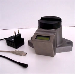
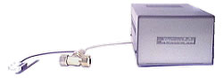
| printable version | Temperature measurement on tool tip TAD | |
| The cutting force measurement is one
aspect in cutting processes. Cutting temperature measurement is the other
aspect, which influences cutting economy in terms of tool-wear and -life.
Both aspects together are really necessary for profund studies in cutting
technique. With this convenient device it is possible to measure any lathe tool temperature touch-free and with very fast reaction time. It is based on an InGaAs-radiation sensor capable of measuring temperatures of a 1mm small spot utmost near to the tool tip. | |
Technical data: Distance to tool tip: 90mm (3.6"); exact adjusting
achieved by pilot lamp | ||
Designs:
| ||
Keywords: Temperature, Temperature on tool
tip, Tool tip temperature, Temerature measurement, Turning, Component
Dynamometer, Tool Dynamometer, cutting thrust meter, wear detection |
||
| ©TeLC Unna 2004 | ||
| printable version | Screw- dynamometer SchKM2010 | |
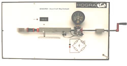
| SchKM2010 is a 2-components dynamometer for measurements on bolt connections. It measures:
Both components are 50% overload resistant. | |
| This way is measured:
| ||
Keywords: Torque meter, Cutting Dynamometer,
Tool Dynamometer, Cutting thrust meter, wear detection, break detection,
Tool monitoring, Drilling, Drill, Borehole, Power, Force, Feed, Cut, Cutting,
Burr, Temperature, Torque, Reduction of wear and tear, wear out |
||
Included in set is an axial roller bearing , which allows to avoid fricton under nut. Suitable experiments are:
|
||
Measures are read directly on the internal digital display or are serially transmitted to PC for data acquisition with TeLC XKM software : plotting, saving, editing and protokol printout. |
||
| ©TeLC Unna 2004 | ||
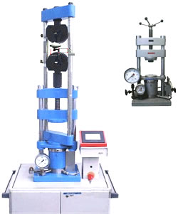
| printable version | Material test machine | |
| Hydraulic universal test machine with integrated control for powerful test applications. | |
Manual control: Touch-screen control for piston-speed and -direction in keying and switching mode. Indicators for current and maximum values of force and displacement. | ||
Measuring systems:
| ||
Tests: | ||
Dimensions: Total (w x d x h): 500mm x 600mm x 1800mm | ||
Devices: Thread clamps, Wedged clamps for sheet material | ||
Power creation: Hydraulic aggregate with speed controlled electric motor,
no use of valves | ||
Keywords: Material test, Material Test Machine,
Test Machine, Universal Test Machine |
||
| ©TeLC Unna 2004 | ||
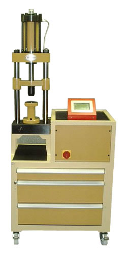
| printable version | Material test press | |
| Hydraulically driven Universal Material Testpress 120 kN / 150 mm stroke for tensile-, compression-, hardness and technological tests of all kind. Machine is equipped with fast and highly resolving electronic measure systems for force and travel and with electrically controllable actors. Machine has got a controlsystem for speed, forcecreation, force start and ending, testcycles, testseries, operator guidance, software, etc The inbuilt intelligency is operated from the touchscreen or the serially connected PC. Singular is the Video
Measure System for Contraction. | |
Software exists
allready for numerous tests. Software can easily be changed / created by
the user himself, e.g.:
| ||
Downloads: | ||
| Machine is available in table and compact version and can come with a huge selection of tools. For more details visit www.oehlgass.de. | ||
Keywords: Upgrade, Oehlgass, Oehlgass, Oelgas,
Oelgass, Modernization, Press, Presses, Update, Sensor, Software, Material
test maschine, Universal, Universal material test machine |
||
| ©TeLC Unna 2004 | ||
| printable version | Upgrades | |
| Upgrade Oehlgass press | Upgrade Weber press | Sensors and software | ||
| This upgrade is a cost advantageous possibilty to provide existing conventional presses and material test machines type "Oehlgass" with modern drive, control, measuring technique and data acquisition. Drive and control: An electric control replaces the existing manual control. So it is possible to provide powerful control commands. The manual control, indication of force and displacement is perfomed by touch-screen. Measuring devices:
| |
Downloads: | ||
| Upgrade Weber press | ||
| This upgrade is a cost advantageous possibilty to provide existing conventional presses and material test machines type "Paul Otto Weber" with modern drive, control, measuring technique and data acquisition. Drive and control: An electric control replaces the existing manual control. So it is possible to provide powerful control commands. The manual control, indication of force and path is perfomed by touch-screen. | |
Measuring devices:
| ||
| Sensors and software | ||
| This upgrade is a cost advantageous possibility to provice older, conventional presses and material test machines with electric displacement and force measurement and modern test software. | |
| Properties:
| ||
Availability: The upgrade suits to most presses and material test machines (for example Oehlgass, Weber, Wolpert and Trebel e.c.). Please ask for your press type! (Contact) | ||
Delivery capacity: Force and displacement sensor, control device, software package, self installation possible. | ||
| nach oben | ||
Keywords: Upgrade, Oehlgass™, Weber,
Wolpert, Trebel, Modernization, Update, Sensor, Software, Material test
maschine, Universal, Universal material test machine |
||
| ©TeLC Unna 2004 | ||
| printable version | Material test software | ||
| This control and data acquisition software package provides multiple material test features supporting our material test machine type. It is also usable with our upgrades for presses and material test machines. | ||
Control: Control of piston speed and direction | |||
| Possible tests:
| |||
Characteristic values: Calculation and derivation of all characteristic values and graphical insertion in the stress-strain-diagram. | |||
Test evaluation: Preconfigured templates for test evaluation. | |||
Test series: Guided execution of consecutive tests with common evaluation. | |||
Interface: Interface to the Video extensiometer. | |||
| Video-software MazeCam | |||
|
| ||
| With this software package it is possible to observe the specimen and determine its real necking cross section size by image processing. | |||
Cross section size measurement: Determination of cross section size to calculate the true stress | |||
Video-camera:
| |||
Technical details: Image processing rate: ca. 5fps, depending on computer
system | |||
Delivery capacity: Video-camera, background light, parallel leader | |||
Keywords: Material test, defined speed of
stress increase, Real Stress, Extensiometer, Video extensiometer, Cross
Extensiometer, Video, Video Observation, Video Recording |
|||
| ©TeLC Unna 2004 | |||
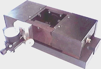
| printable version | Hydrodynamic bearing | |
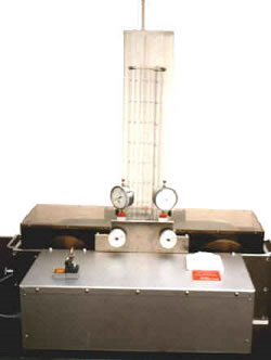
| The hydrodynamic bearing is such
a fundamental machine element, that every student should have knowledge
about it. This bearing competes with the ball bearing, but the advantages
are obvious. Though we meet the hydrodynamic bearing foremost in its cylindrical
form, a suitable way to learn about it is the plate form. The model uses a belt drive that submerges downtrum into an oil reservoir . So transports oil on its surface. Upside a plate is placed which can be inclined and the distance to the belt adjusted. Above the plate a number of glas tubes is arranged having connection with the oil film via small bores. The tubes are graduated so is readable the pressuredistribution of the oilfilm. | |
| Parameters which define the portability of the bearing are:
| |
| Attributes of the device:
| |
| These relations are determined erperimentally with the device. | ||
| ©TeLC Unna 2004 | ||
| printable version | Sensors | |
| The 90 cm long model is made for the experimentally detection of different relations between values that are in use in machine technics. Attributes of the model:
| |
| ©TeLC Unna 2004 | ||
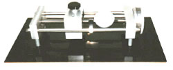
| printable version | Ballspindle | |
| Ballspindles are used to improve the properties of a normal spindle drive with respect to reduction of friction and increase of speed. Ballspindles are very important elements in the drives of toolmachines. They compete today with the direct magnetic drive. The accuracy does not only depends on spindle and nut it also | |
| depends on the bearing of the locked spindle end. To reduce play, the baring and nut can be adjusted stiffer. But not to forget is the fact, that a certain play is simply necessary for lockfree running under temperature expansion. So all this is a question of clean adjustment. This model was made to train this aspects. | ||
Description: The model has got a loading device in the form that a slide can be differently pressed against the traversebolts. The spindledrive now has to overcome the more resistance, the stronger upper and lower slide are screwed together. The handwheel has got the scaling 250. This corresponds to the spindle gradient 2.5 mm The dial gauge 5mm/0.001mm is set axially against the spindlenut to measure play. |
||
Experiments:
|
||
| ©TeLC Unna 2004 | ||