Dipl. Ing. A. Kutschelis & Sohn
Technische Lehrmittel Construktion
D- 59425 Unna
Germany
web: http://www.telc.de
mail: mail@telc.de
phone.: +49 (0) 2303 239999
facs: +49 (0) 2303 239990
| printable version | Sort and test cell | ||
Portal with PLS |
|||
|
|
||
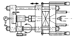
| The cell realizes an assorting and inspection process. The assorting is with respect to the weight of the cylindrical objects. The weighing is a pneumaticallly balanced semibeam with strain gage sensor as comparator. The balancing is a control task for the PLS and its ADC and DAC components together with the control PID-algorithm. After weighing different decisions are provided: placement in rising weight order on the rack or offsorting and elimination out of the unit etc. | |||
working area 600 x 600 x 300 mm3
with the following processelements:
|
Use of all possibilities of the
PLS:
|
||
Variation of systems:
|
|||
| ©TeLC Unna 2004 | |||
| printable version | Automated injection moulding machine SP3K | |||||||||
|
Injection Moulding Machine SPK97 is also an application model for PLC, pneumatics, hydraulics and tool making. The machine on rollable stand is small, surveyable, transparent and less dangerous. Heat and force effected parts are carefully isolated. |
|||||||||
Build-up: Modern original industry components:
|
||||||||||
Control: Use of a compact PLC with the following attributes:
|
||||||||||
| Cycle:
|
|
|||||||||
Injection unit and locking:
|
|
|||||||||
Moulds: Moulds in original design with the following characteristics:
|
||||||||||
Technical Details:
|
||||||||||
Keywords: Injection Moulding Machine, Pneumatik,
Thermoplastics Processing, mouldmaking, Pneumatik, Thermoplastics Processing,
Extrusion Blow Moulding Machine, Injector Nozzle, Plastics Compound, Plastics-Processing |
||||||||||
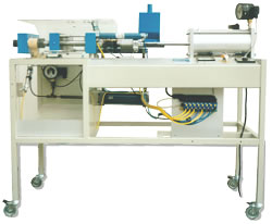
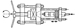
| Manual injection moulding machine SP2 | ||||||||||
|
Handoperated Injection Moulding Machine SP2K with laying coaxial design, pneumatically driven piston and handspindle-locking. |
|||||||||
Injection unit:
|
||||||||||
Moulds: Tensile- and impact specimen, spiral , screwdriver, free selectable ingraving . |
|
|||||||||
Technical Details:
|
||||||||||
Keywords: Injection Moulding Machine, Pneumatik,
Thermoplastics Processing, mouldmaking, Pneumatik, Thermoplastics Processing,
Extrusion Blow Moulding Machine, Injector Nozzle, Plastics Compound, Plastics-Processing |
||||||||||
| ©TeLC Unna 2004 | ||||||||||
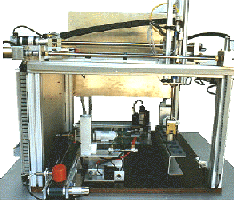
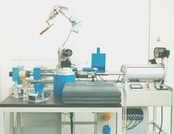
| printable version | Manufacturing cell with injection moulding machine and robot | |
|
This cell combines our automated injection moulding machine SP3K with a robot. The result is a manufacturing cell with the process steps feeding, unloading, removing the sprue, checking and final packing. |
|
Build-up:
|
||
Procedure:
|
||
Keywords: Process cell, injection moulding
machine, automation technology , industrial robotics, handling, manufacturing
cell |
||
| ©TeLC Unna 2004 | ||
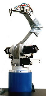
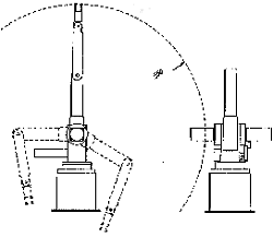
| printable version | Robot | ||||||||||
|
small intelligent arms
Robot for pick and place and coating The robot is for point-to-point operation. At 20% speed it is possible to execute any linear or circular paths continously. Therefore it is well usefull for distributing and coating purposes f.e. of glue or sealants.
Two fingers hand in basic configuration. Additional functions are possible. |
||||||||||
|
|||||||||||
| ©TeLC Unna 2004 | |||||||||||
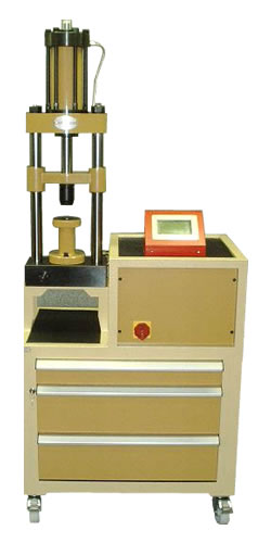
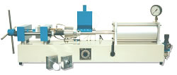
| printable version | Material test press | |
| Hydraulically driven Universal Material Testpress 120 kN / 150 mm stroke for tensile-, compression-, hardness and technological tests of all kind. Machine is equipped with fast and highly resolving electronic measure systems for force and travel and with electrically controllable actors. Machine has got a controlsystem for speed, forcecreation, force start and ending, testcycles, testseries, operator guidance, software, etc The inbuilt intelligency is operated from the touchscreen or the serially connected PC. Singular is the Video
Measure System for Contraction. | |
Software exists
allready for numerous tests. Software can easily be changed / created by
the user himself, e.g.:
| ||
Downloads: | ||
| Machine is available in table and compact version and can come with a huge selection of tools. For more details visit www.oehlgass.de. | ||
Keywords: Upgrade, Oehlgass, Oehlgass, Oelgas,
Oelgass, Modernization, Press, Presses, Update, Sensor, Software, Material
test maschine, Universal, Universal material test machine |
||
| ©TeLC Unna 2004 | ||