Dipl. Ing. A. Kutschelis & Sohn
Technische Lehrmittel Construktion
D- 59425 Unna
Germany
web: http://www.telc.de
mail: mail@telc.de
phone.: +49 (0) 2303 239999
facs: +49 (0) 2303 239990
| printable version | Transparent engine | |||||||||||||||||||
|
| |||||||||||||||||||
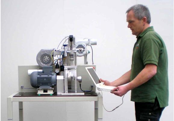
The well known Transparent
engine coupled with our power absorber and equipped with our systems explains
the internal combustion process of a 4-stroke Otto engine better than anything.
Newly equipped it matches the requests on explaining the future automotive
methodes fundamentally:
| ||||||||||||||||||||
All these features
should result to:
| ||||||||||||||||||||
| The measuring system enables the evaluation. | ||||||||||||||||||||
| Fully variable valves actuation –
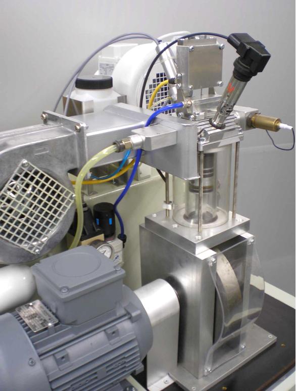
timing and lift – for a laboratory The 4-stroke engine which is well known for many years in laboratory practice was equipped with a piezo-pneumatic valve actuator. The performance is controlled with the mouse pointer of the PC during running. The engine is incorporated in a test rig whose control, data acquisition and data display is exclusively executed on the PC. The real-time data acquisition includes the permanent indicating with displaying in p/V or p/? - diagram and with the calculation of the averaged indicated pressure. | |||||||||||||||||||
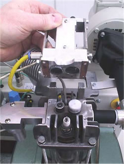
| 1. The engine The engine base is a mono-cylinder with 70 ccm stroke volume and a compression ratio of 1:4. The cylinder wall is glass. The piston runs dryly. The connection-rod bearings are dryly running needle rollers. The transparent design of the engine allows observation of crankshaft, piston, valves, ignition and combustion. Figure 1 The usable speed range is between 350 and 2500 rpm. The hanging valves are directly operated by cup-like pneumatic pistons (Figure 1). The auxiliary pressed air flow is conducted by a way-valve that is driven by a piezo-actuator. The high flow-rate of this fast way-valve makes this functionality possible. The mixture is made by an injection pump in the intake. The pump performs a mono-stroke of adjustable height, driven by a piezo-actuator. Partial load is preferably executed by “Early intake valve closure” or “Late intake valve closure”, but it is also possible to activate one throttle situation in | |||||||||||||||||||
| the intake for comparison.
Reducing the pressure of the auxiliary air from 2,8 down to 2.0 bar effects
a reduction of the valve lift and thus a reduction of the time opening square.
The electronic ignition is also fully variable in terms of timing and dwell. The upper panel of the software screen contains the control elements (Figure 2) : A status- and a speed shifter control the engine performance. The engine needs a high resolution field of characteristic data sets for all operation conditions. These have to be elaborated by the student and are saved as data files. With loading of such a data file the engine is immediately driven into the operation point, including the set speed. The control elements for saving and loading can be found in the control panel of the screen. (Figure 2). | ||||||||||||||||||||
| ||||||||||||||||||||
| 2. The test rig Important part of the test rig is the directly coupled electric motor/generator. A special elastic shaft joint governs the extremely disharmonic force transmission of the mono-cylinder. The electric motor/generator is in swivel bearings and has got a torque adaptor which is combined with a force sensor. The electric engine governs the combustion engine and functions as power absorber and engine starter. The engine needs an additional piston cooling by an air ray similar to the piston cooling with oil spray. This is automatically controlled by the test stand depending on exhaust temperature and power. The exhaust gas is cleaned by a special catalytic converter. A fan leads the exhaust gas through a pipe and a flex hose to the outside. | ||||||||||||||||||||
3. Measured quantities
The data acquisition captures 40 samples of each non-indicated measured quantity per revolution. The quantities value is equal to the arithmetic average. The resolution for the indicator diagram is 200 values per power cycle. The control timing actions are refreshed 400 times per power cycle. | ||||||||||||||||||||
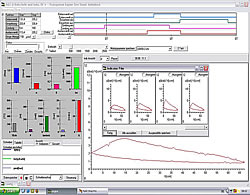
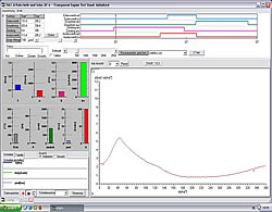
| 4. The measuring display All measured quantities as well as the derivative quantities power, specific fuel consumption and average internal pressure are displayed by bargraphs. A fast refreshing table displays all quantities as exact digitals. All values can be selected for plotting. An extraordinary feature is the test stand's indicator mode which works simultanously to all other functions. The data is displayed on a software-oscilloscope. Figure 3 shows a minimized p/alpha-diagram and an enlarged one in figure 5. The indicator diagram can be configured as p/? or p/V diagram with optional focus on the gas exchange phase ((Figure 7). Not only the internal cylinder pressure is indexable, but also torque, intake air flow and voltage of the oxygene probe. ((Figure 4 u. (Figure 6) Indicator diagrams can be saved with the indicator diagram browser, presenting the recently captured diagrams for further evaluation. Stored data files includes the values of all quantities, especially the control timings. A powerfull export function provides easy export to external software. The software package includes powerfull functions for the post editing of recorded data and preconfigured evaluation templates (Figure 8). Finally | ||||||||||||||||||||
|
| |||||||||||||||||||
|
| |||||||||||||||||||
|
| |||||||||||||||||||
Keywords: engine dynamometer, engine test
cell, engine tester, engine test stand, testcell, motor tester, engine
test software, power tester, transparent engine, 4-cycle engine, oil-free
engine, engine test stand,power absorber, internal combustion test bed,
4-cycle engine trainer, automotive education, Valvetronic, Transparent
Engine Technique Stand,fully variable valve actuator, monocylinder 4-stroke
Otto, transparent cylinder, crankshaft, piston, valves, ignition, combustion,
different fuels, intake injection,Injection volume, timing are fully variable
adjustable, intake, outlet, open,close, valve lift, time opening square,
electronic ignition, free variable, dwell, cathalyst, intake airvolume,
exhaust tubing, oxygene probe exhaust gas temperature, rendered torque,
force sensor, sviwel support, rollable stand, ignite, inject,air fuel
mixture, rich, poor, fuel injection, ignition and valves timing, ignition,
early, late, inlet outlet valve overcross, Indicating mode, internal cylinder
pressure, intake valve, outlet valve, compress, cold start, warm up, injection
quantity, Compression curve, long ignition delay, Late intake closure,inflammation,
Early intake closure, fluid condensation, specific fuel consumption, stoichiometric
mixture, variable valve actuator, throttle, Partial load, early inlet
valve, late inlet valve close, gas exchange phase, indicating aspirated
air flow, indicating torque, 4 stroke engine, effect of ignition, valve
lift, vva, VVA |
||||||||||||||||||||
| ©TeLC Unna 2004 | ||||||||||||||||||||
| printable version | |||||||
| First internal combustion engine to be operated as 4-stroke and 2-stroke | |||||||
| The small engine for laboratory practice, which is already famous for its fully variable valves actuation , was redesigned so that it can be operated either in 4-stroke or in 2-stroke mode. This is possible, because all its functions are controlled completely electronically. The new direct injection, which was realized with the reinforced piezopump, allows injection into compression stroke after ending of the flushing phase. Flushing is made by the correct setting of the valves open phase around LDC and with flushing air which is taken from the pressed air supply, always used with the engine. Control and data acquisition is done from PC screen same like before. Also loading and saving of data sets of performance conditions like coldstart, fulload800, partialload800 etc. are done same way as before during running. So can be switched completely freely also between 2-stroke and 4-stroke data sets. Flushing air supply however should be disconnected in 4-stroke mode. Otherwise the engine would be overcharged.
Regarding this the new design provides not only the 2-stroke operation but also the overcharging of the engine. | ||||||
| |||||||
Screen with: | |||||||
|
| ||||||
Stichworte: Motortechnik Übungsstand, Leistungsprüfstand, Motorleistungsprüfstand, Ventilverstellung, Indizieren, Viertakt Motor Modell, Ottomotor Modell, Motorprüfstand Messtechnik, Motorprüfstand Datenerfassung, Verbrennungsprozess, Ventilsteuerung, Druckindizierung, Motorprüfstand, Glaszylinder-Motortechnik-Stand, Megatech, Glaszylinder, variable Ventilsteuerung, 4-Takt-Ottomotor, 4 Takt Motor, 4 Takt Otto Motor, gläserner Zylinder, transparenter Zylinder, Kurbeltrieb, Kolben, Ventile, Zündung, Verbrennung, verschiedene Kraftstoffe, Saugrohr-Einspritzung, Einspritzung, Einspritzmenge, Einspritzzeitpunkt, Einlass, Auslass, Ventilhub, Zeit-Öffnungs-Querschnitt, elektronische Zündung, Kennfeldzündung, Schließwinkel, geregelter Katalysator, Kurbelwellenstellung, Lambda-Sonde, Abgastemperatur, Drehmoment, Motorbetriebszustand, Zünden, Einspritzen, Kraftstoffmenge, Ventilsteuerzeiten, Frühzündung, Spätzündung, Überschneidung, Einlassventil, Auslassventil, Einlaßventil, Auslaßventil, Kennpunkt, Kennfeld, Indizieren, Zylinderinnendruck, Motordrehmoment, angesaugte Luftmenge, Expandieren, Auswerfen, Ansaugen, Verdichten, Warmlauf, Kaltstart, Indikatordiagramm, Vorzündung, gute Gemischbildung, Steuerverfahren, Laststeuerverfahren, Spätes Einlass Öffnen, Spätes Einlaß Öffnen, Spätes Einlass Schliessen, Spätes Einlass Schließen, Wandkondensation, Kraftstoffverbrauch, Kurbelwellenwinkel, Laufgrenze, fett, mager, stöchiometrisches Verhältnis, P/V-Diagramm, Drosselklappe, Gaswechselschleife, Vollast, Teillast, Volllast, Teilllast, Verlustminimierung, Vier-Takt-Motorbremse, Motorbremse, völlig variable Ventilsteuerung, variable Steuerzeiten, Lambda-1-Technik, Magerbetrieb, Leistungssteuerung, Valvetronic |
|||||||
| See also : Transparent engine | |||||||
| ©TeLC Unna 2004 | |||||||
| printable version | Hydrobrake | |||||||||
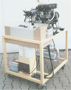
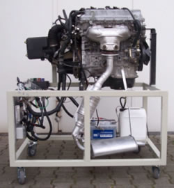
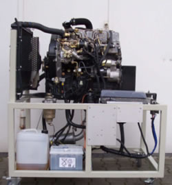
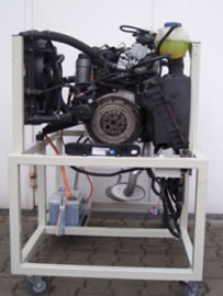
| Small moveable, powerful engine test stand providing high measuring accuracy, maximum safety, clear build-up und easy start-up. Systems:
| |||||||||
| Measuring devices: The measuring devices are digitally connected to the internal controller, sending serial data to an external PC. Stand control and data acquisition is performed by Windows-software: | ||||||||||
Control indicators: Oil pressure, Water temperature, Load | ||||||||||
Technical details: Maximum power: 100kW | ||||||||||
| ||||||||||
Keywords: Engine test cell, Engine test stand,
Engine test bed, automotive education, 4-cycle engine, 4-stroke engine |
||||||||||
| ©TeLC Unna 2004 | ||||||||||
| printable version | Hydrobrake sectioned version | |
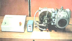
| Hydrobrake 100 kW / 6000 rpm in
sectioned version is an engine test-
| |
| Functional
engines, which are only operated under idling conditions , can easily
be modified for power- and consumption testing. | ||
Modification of Functional engines:
| ||
Engine-
test- and Control- Software | ||
Keywords: Engine test cell, Engine test stand,
Engine test bed, automotive education, 4-cycle engine, 4-stroke engine |
||
| ©TeLC Unna 2004 | ||
| printable version | Tandem 2 engines test cell | |||||||||
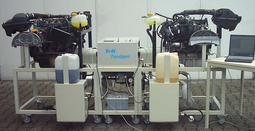
| Engine test cell "Tandem 100kW / 6000 Rpm" includes a Diesel and a Gasoline engine, the one or other connectible with the power absorber just on knob-turn, so providing fast and profund comparison of both engine types with no need of resetting work. Measurement not only of power and fuel consumption but also:
| ||||||||||
| ||||||||||
| Tandem is controlled by PC. | ||||||||||
| Specialties: The measuring devices are digitally connected to the internal controller, sending data to an external PC. Stand control and data acquisition is performed by Windows-software. Measured quantities are:
| ||||||||||
Safety: The brake implements a safety guard system preventing over-speed and water-pressure-lacking. Turning and hot parts are shielded. | ||||||||||
| ||||||||||
Keywords: Engine test cell, Engine test stand,
Engine test bed, automotive education, 4-cycle engine, 4-stroke engine |
||||||||||
| ©TeLC Unna 2004 | ||||||||||
| printable version | Small engine test stand "HydroSachs" | |||||
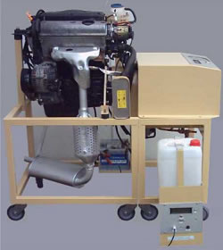
| Small, compact, air-cooled engine test stand providing high measuring accuracy, maximum safety and clear build-up. It needs no supply like cooling water and therefore allows fast and easy start-up. It is available with Diesel and Gasoline engines, working in 2 or 4 stroke process. A special feature is the inbuild indicating system. Data acquisition and processing will be performed by our powerful engine software package. | |||||
Measuring devices: The measuring devices are digitally connected to the internal controller, sending serial data to an external PC. Stand control and data acquisition is performed by Windows-software. Measured quantities are: | ||||||
Technical data: Maximum power: 5kW (Gasoline- and Diesel-engines) | ||||||
| ||||||
Keywords: Engine test cell, Engine test stand,
Engine test bed, automotive education, 4-cycle engine, 4-stroke engine |
||||||
| ©TeLC Unna 2004 | ||||||
| printable version | Indicating | |||||||||
| his Indicating System includes hardware and software providing indicated measurement of fast reacting quantities measured in combustion engines and compressors. | ||||||||||
Technical data:
| ||||||||||
| ||||||||||
| Please ask for further indexable quantities like lambda probe signal. | ||||||||||
Available diagram types Every indicated quantity can be presentated versus crank shaft angle alpha or current cylinder volume V. | ||||||||||
Derivative quantities Speed, crank shaft position, averaged indicated pressure, delivery | ||||||||||
Diagram browser Every cycle of the engine is captured and presented in the diagram browser providing further processing methods for each diagram. | ||||||||||
| ||||||||||
Keywords: Indicating, Internal cylinder pressure,
P/V-Diagram, P/alpha, Diagram |
||||||||||
| ©TeLC Unna 2004 | ||||||||||
| printable version | Software for engine test | |
| Engine test stand software for the Windows operating systems 95/98/NT/2000/ME/XP | ||
| ||
| Total view includes
plotter, bars and small oscilloscope to view the
| |
| Indicating view
with large oscilloscope, presenting the p/V,( p/alpha)-chart and small plotter
for other quantities. The oscilloscope-presentation is fast refreshing, depending on computer-performance up to 20 times per second. Each combustion-cycle is captured. An indicator diagram browser allows confortable data storage to disk. | |
| This test evaluation, shows multiple p/alpha-charts with different ignition timings. | |
Stichworte: Software Motortechnik |
||
| ©TeLC Unna 2004 | ||
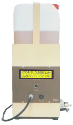
| printable version | Fuel consumption meter | |
| This universal fuel consumption meter of high accuracy can be used with gasoline and diesel engines. Supply systems having fore- and back flow are connected with quick connectors and if needed supplied by the built-in fuelpump. Build-up: The unit includes the reservoir of 10L ( 20L ). Measuring
principle is precision time measurement of a down flowing volume. Extensions:
Technical details: Measuring range: 0.01 - 1 L/h and 0.5 - 40 L/h; | |
Keywords: Fuel consumption meter, Fuel, Fuel
consumtion, Econometer, Consumption meter, Flow measuring device, Sensor,
Fuel meter, Flow meter |
||
| ©TeLC Unna 2004 | ||
| printable version | Functional engines | ||||||||||
| Functional Engines are the necessary training object for automotive service technicians. With help of the test- equipment engine functions are verified, faults are found and can be repaired. All components are close together and easy reachable. Included systems are complete for engine operation.
Faults insertion box:
| ||||||||||
| |||||||||||
| |||||||||||
Keywords: Engine test cell, Engine test stand,
Engine test bed, automotive education, 4-cycle engine, 4-stroke engine
|
|||||||||||
| ©TeLC Unna 2004 | |||||||||||
| printable version | FuMoControl | ||
| Control- and Communication Unit for Functional Engines (FuMoControl and FuMoWin32) | |||
Stichworte: Motortechnik Übungsstand, Motorleistungsprüfstand, Leistungsprüfstand, Wirbelstrombremse, Motorprüfstand Messtechnik, Motorprüfstand Datenerfassung |
|||
| Better Training in Automotive Practice workshop to match the skill requests modern engine electronic equipment demand. TeLC developed FuMoControl a new scope on training engine control electronics. Main features of FuMoControl are:
Advantages:
Interfacebox On the engine support contains the control- , switching and communication unit with terminals(RS232, USB, Ethernet) as well as an LCD and a navigation- turnknob for the execution of basic functions. Following pictures show screen displaying, saving actions and Scheme |
|||
|
|||
|
|||
|
|||
| ©TeLC Unna 2004 | |||
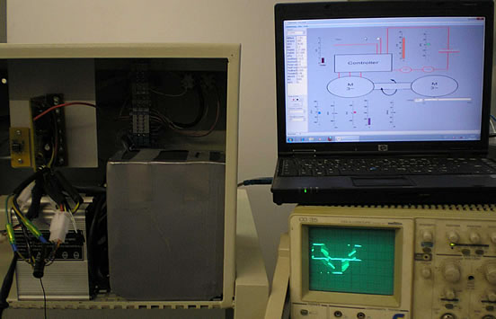
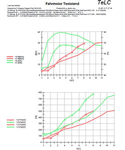
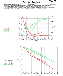
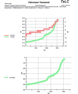
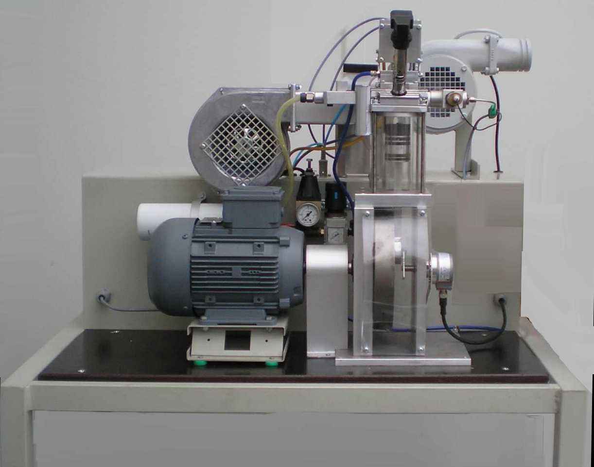
| printable version | torquemotor-teststand | ||||||||
Electrification of vehicle drives is coming up more and more. The battery is the most important object. Till today weight of the enery content is 10 times of that with gasoline. And the costs are a lot. Energy balance is only then ok if charging current is generated by regenerative means. All these developments are going on. If the battery is heavy then the vehicle itself must be eased, new material is being developped for that purpose. | |||||||||
| |||||||||
Build-up:
| |||||||||
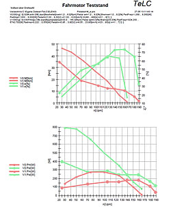
Technical data of the teststand:
| |||||||||
The operational functions on the teststand:
| |||||||||
Experimental possibilities:
| |||||||||
| Discrete Measurement on in- and outputs of the controller Part of the cabinet can be opened from behind. Controller, charger, battery and all connectors are visible and accessable. With help of external measure instruments status, voltages and currents can be measured. | |||||||||
| |||||||||
| TeLC software: Acquisition screen as process image or as plotter see below. Included are remote control and switching functions. | |||||||||
| |||||||||
| |||||||||
| Reports of some typical tests Multiple data files can be plotted with predefined graphs..Data were concentrated (edited) Tableform data export f.e. to Excell is provided | |||||||||
| |||||||||
Stichworte: Motortechnik Übungsstand, Leistungsprüfstand, Motorleistungsprüfstand, Ventilverstellung, Indizieren, Viertakt Motor Modell, Ottomotor Modell, Motorprüfstand Messtechnik, Motorprüfstand Datenerfassung, Verbrennungsprozess, Ventilsteuerung, Druckindizierung, Motorprüfstand, Glaszylinder-Motortechnik-Stand, Megatech, Glaszylinder, variable Ventilsteuerung, 4-Takt-Ottomotor, 4 Takt Motor, 4 Takt Otto Motor, gläserner Zylinder, transparenter Zylinder, Kurbeltrieb, Kolben, Ventile, Zündung, Verbrennung, verschiedene Kraftstoffe, Saugrohr-Einspritzung, Einspritzung, Einspritzmenge, Einspritzzeitpunkt, Einlass, Auslass, Ventilhub, Zeit-Öffnungs-Querschnitt, elektronische Zündung, Kennfeldzündung, Schließwinkel, geregelter Katalysator, Kurbelwellenstellung, Lambda-Sonde, Abgastemperatur, Drehmoment, Motorbetriebszustand, Zünden, Einspritzen, Kraftstoffmenge, Ventilsteuerzeiten, Frühzündung, Spätzündung, Überschneidung, Einlassventil, Auslassventil, Einlaßventil, Auslaßventil, Kennpunkt, Kennfeld, Indizieren, Zylinderinnendruck, Motordrehmoment, angesaugte Luftmenge, Expandieren, Auswerfen, Ansaugen, Verdichten, Warmlauf, Kaltstart, Indikatordiagramm, Vorzündung, gute Gemischbildung, Steuerverfahren, Laststeuerverfahren, Spätes Einlass Öffnen, Spätes Einlaß Öffnen, Spätes Einlass Schliessen, Spätes Einlass Schließen, Wandkondensation, Kraftstoffverbrauch, Kurbelwellenwinkel, Laufgrenze, fett, mager, stöchiometrisches Verhältnis, P/V-Diagramm, Drosselklappe, Gaswechselschleife, Vollast, Teillast, Volllast, Teilllast, Verlustminimierung, Vier-Takt-Motorbremse, Motorbremse, völlig variable Ventilsteuerung, variable Steuerzeiten, Lambda-1-Technik, Magerbetrieb, Leistungssteuerung, Valvetronic |
|||||||||
| ©TeLC Unna 2004 | |||||||||